5. X AIR for iPad
The X AIR applications for iOS, Android and Windows/Mac/Linux allow all of the physical controls and features normally found on analog mixers to be adjusted digitally, and also allow effects and routing to be fully adjusted, all from a remote location away from the input box. This results in a very compact, yet full-featured mixing solution that can be operated while moving about the venue or studio. This chapter will discuss the software's functionality on an iPad.
5.1 Main Screen
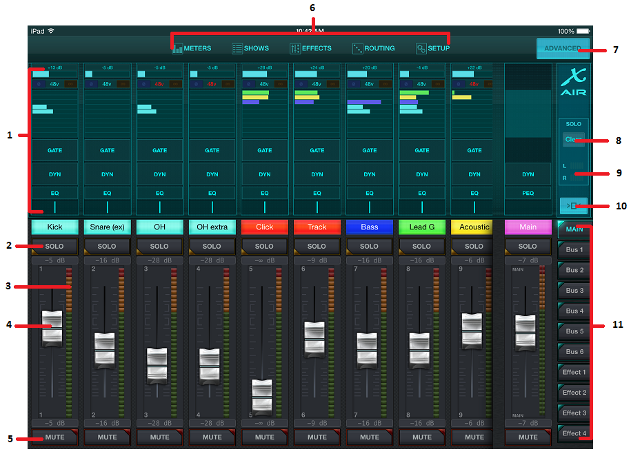
e main screen provides access to all 16 channel faders, Aux in, and FX send levels, as well as navigation to preamp controls, meters, FX slots and more. The channel strips can be swiped side to side to reveal all 21 faders, and the selected bus fader is always visible.
-
The Channel Strip control section gives a quick reference to the status of phantom power, aux send levels, pan, etc., but no adjustments are made directly on this screen. Touch anywhere inside a channel’s top strip section to edit parameters.
-
Touch a channel’s Solo button to send the channel to the solo bus. The button will light yellow to indicate that a channel has been soloed.
-
Each channel has a dedicated meter to monitor the input level. If the meter reaches the red clip lights, lower the gain control on the Input screen (5.2).
-
The Channel Fader adjusts a channel’s level, or adjusts the aux/FX send level, depending on which layer is selected on the right-hand side (see callout 11).
-
Touch a channel’s Mute button to mute the channel. The button will light red when muted.
-
The Meters, Shows, Effects, Routing and Setup buttons allow direct access to these menus.
-
The Advanced button only applies to the Gate and Dynamics sections (5.4 and 5.5).
-
The Solo Clear button releases all soloed channels.
-
The Solo Meter shows the level of the solo bus.
-
The Channel Width button toggles between normal and condensed channel strip views. When active, the channel strips provide more detail and additional room to touch the desired fader or button, while the condensed view allows all 16 inputs to be viewed simultaneously. In either view, the strips must be swiped to the left to access the FX send levels.
-
The Fader Bank buttons alter the function of the channel faders. When set to Main, the faders adjust the channel volume levels sent to the main bus, and the overall main output. When one of the Aux or Effect buttons are selected, the faders adjust each channel’s send level to that bus for monitoring or effects routing. The level for the Aux or Effect bus that is currently selected can be adjusted where the main fader normally appears.
5.2 Input
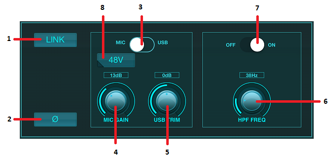
The Input section allows adjustment of the most common preamp parameters such as gain and phantom power. This is accessed by pressing the top of the Channel Strip of the channel you wish to modify. If another menu such as Sends or Gate come up instead, the menus can be swiped side-to-side without returning to the Main Screen.
-
The Link button allows adjacent channels to be linked as a stereo pair. Moving one of the linked channels' fader will also adjust the other channel.
-
The Phase button inverts the phase.
-
Use the Mic/USB switch to determine whether the channel is fed by the microphone input or by a signal from a DAW via the multi-channel USB connection.
-
The Mic Gain knob adjusts the input gain for the currently selected channel’s mic preamp.
-
The USB Trim knob adjusts the digital trim for the signal coming from the connected computer. The Mic/USB switch must be set to USB.
-
The HPF Freq knob adjusts the frequency of the filter, allowing unwanted low frequencies to be removed.
-
Engage the HPF (high-pass filter) with this switch.
-
Press this button to engage the phantom power.
5.3 Sends
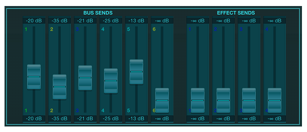
The Sends tab allows the currently selected channel’s signal to be routed to the 6 Aux outputs and to the 4 Effects processors. Aux and Effects routing can also adjusted using the fader banks on the right-hand side of the screen.
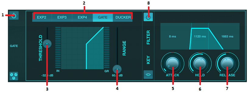
5.4 Gate
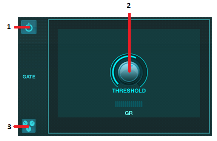
The Gate tab allows a noise gate to be engaged and adjusted to remove unwanted noise. To accommodate various levels of mixing expertise, a standard or advanced screen can be selected. The standard view offers 4 presets and a threshold adjustment, while the advanced view allows fine adjustment of the gate parameters.
-
Engage the gate with the on/off button.
-
Adjust the Threshold that the audio must reach in order to bypass the gate. Any audio that does not register beyond the threshold setting will be muted automatically.
-
Press this button to open the preset list where your settings can be saved can recalled.
-
Engage the gate with the on/off button.
-
Gate Type buttons allow various types of gates to be selected. The EXP2, 3 and 4 settings reduce the output by varying amounts, allowing a natural-sounding reduction of signals that don’t reach the selected threshold. The Gate setting enables a more aggressive drop in volume for signals below the threshold. An additional Range parameter adjusts the amount of attenuation. The Ducker setting attenuates the signal by a predetermined amount whenever the signal rises beyond the selected threshold. The Range parameter adjusts the amount of attenuation for this setting as well.
-
Adjust the Threshold that the audio must reach in order to bypass the gate or engage the Ducker.
-
The Range parameter adjusts the amount of signal attenuation for the Gate and Ducker settings.
-
Adjust the Attack knob to set how quickly the gate takes effect when the input signal drops below the threshold.
-
Adjust the Hold knob to set how long the input signal must surpass the threshold before bypassing the gate.
-
Adjust the Release knob to set how quickly the gate releases after the audio rises above the threshold.
-
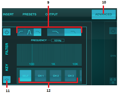
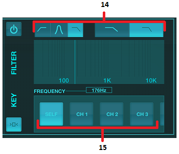
Engage the Key Filter with the on/off button.
-
Select a high-pass, low-pass or mid peak frequency and slope for the key filter. The specific frequency can be selected by dragging the line across the frequency chart.
-
Press the Advanced button to select between normal and advanced gate operation.
-
Access the Key Filter parameters by pressing this button.
-
Select a source for the key filter.
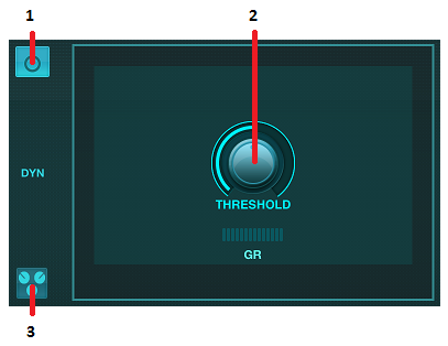
5.5 Dynamics
A channel’s dynamics can be adjusted on this page. A compressor is useful for reducing the dynamic range of a signal, allowing the perceived volume in the mix to be raised without clipping. An expander can add dynamics by attenuating a signal when it drops below the predetermined threshold.
-
Engage the compressor with the on/off button.
-
Adjust the Threshold at which the compressor begins to take effect. Audio that falls below this setting will remain unaffected.
-
Press this button to open the preset list where your settings can be saved can recalled.
-
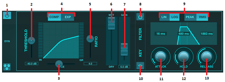
Engage the dynamics processor with the on/off button.
-
Adjust the Threshold at which the compressor begins to take effect. Audio that falls below this setting will remain unaffected.
-
Adjust the Knee to allow the compressor to have a more gradual effect on the signal. When the Knee is set fully to the left (hard knee), any signals that rise above the threshold will receive the full compression ratio right away.
-
Select between a compressor or expander to set the action of the dynamics processor.
-
Adjust the Ratio to determine how aggressively the dynamics are affected.
-
The Wet/Dry ratio determines how much of the signal is left unaffected by the processor.
-
Use the Gain fader to compensate for changes in level caused by the processor.
-
Engage the Key Filter with the on/off button.
-
Select between an aggressive Linear or smooth Logarithmic operation, and between Peak or RMS input response. RMS is most common in compressors, and responds to the average level of incoming audio, whereas the Peak setting responds to brief spikes in loudness that would be allowed through when set to RMS.
-
Access the Key Filter parameters by pressing this button.
-
Adjust the Attack knob to set how quickly the compressor takes effect when the input signal rises above the threshold.
-
Adjust the Hold knob to set how long the compressor takes to enter the release cycle once the audio drops below the threshold.
-
Adjust the Release knob to set how quickly the compressor releases after the audio drops below the threshold.
-
Select a high-pass, low-pass or mid peak frequency and slope for the key filter. The specific frequency can be selected by dragging the line across the frequency chart.
-
Select a source for the key filter.
5.6 Channel EQ
-
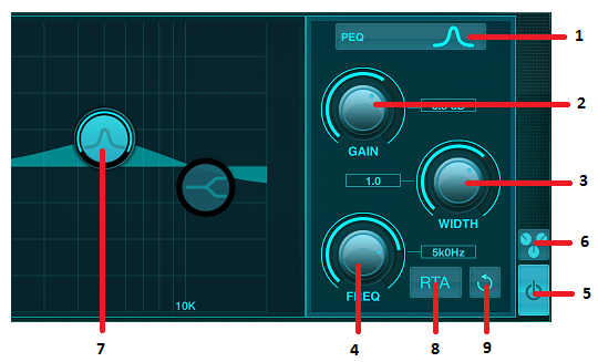
Select the type of EQ for each of the 4 bands. Typically cut or shelf EQs are used for the highs and lows, whereas PEQ (parametric) and VEQ (vintage) are used for the mid range adjustments.
-
Use the Gain knob to adjust the desired boost or cut to the selected frequency.
-
Adjust the Width (Q) to determine how wide or narrow the frequency adjustment will be.
-
Use the Freq(uency) knob to select the center frequency for PEQ and VEQ types, and the starting frequency for cut or shelf EQs.
-
Engage the EQ with the on/off button.
-
Press this button to open the preset list where your settings can be saved can recalled.
-
Press one of the band buttons to select the band. Drag the button left/right to set the frequency, and up/down to set the boost or cut. The desired band must be selected before adjusting the width parameter.
-
Engage the RTA (real time analyzer) with this button. The RTA is pre-EQ by default, but can be adjusted on the Setup - Audio/MIDI page.
-
Press this button to reset the currently-selected band.
5.7 Insert
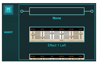
Press the folder icon to engage the insert effect. Scroll through the list of effects blocks to select the desired routing.
5.8 Presets
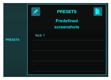
The Presets tab allows channel presets to be recalled, edited and saved. Press the page icon on the right to save a new preset. Press the pencil icon to edit or delete a preset, and press on one of the saved presets to save changes or load that preset.
5.9 Output
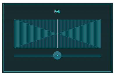
The panorama can be adjusted to position the channel in the stereo field.
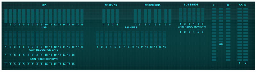
5.10 Meters
The Meters page is accessed via the icon at the top of the main screen. This page allows easy monitoring of all analog and digital levels, including USB channels, Gate and Dynamics activity, P-16 channels and the Main and Solo buses.
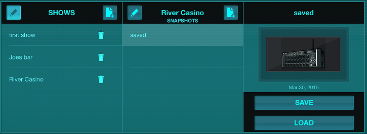
5.11 Shows
The Shows page allows performances to be saved for various venues, artists, sets and arrangements for later recall. Within those shows, individual snapshots can be saved, edited and recalled. Press the page icon to save a new show or snapshot. Press the pencil icon to edit or delete a saved show or snapshot. Pressing on a show or snapshot will allow any changes to be saved, or for a new snapshot to be loaded.
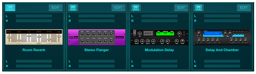
5.12 Effects
The Effects page is accessed via the icon at the top of the main screen. There are 4 slots where various effects can be selected and adjusted to suit the application. Press the folder icon to activate an effect block. Press Edit to select a different effect, and press on the effect graphic to edit parameters. See the Effects Descriptions chapter for more details.
5.13 Routing
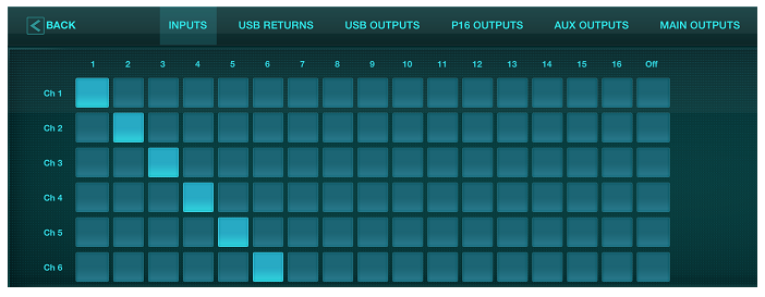
The Routing page allows the analog and digital inputs and outputs to be reassigned to different destinations. Select the group of inputs or outputs you want to edit from the top row, then press the block to which you want to reassign a channel.
5.14 Setup
The Setup page is accessed via the icon at the top of the main screen. This allows the channel layout to be modified, a console reset, and network settings to be adjusted.
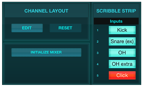
Press the Edit button to reorder the input, aux and effects channels. To return to the standard configuration, press the Reset button. To reset the mixer to factory settings, press the Initialize Mixer button, then press Yes to confirm.
The scribble strips are also edited on this page. Press a channel's blank box to assign a color and name for that channel. The buses and effect blocks can also be edited.
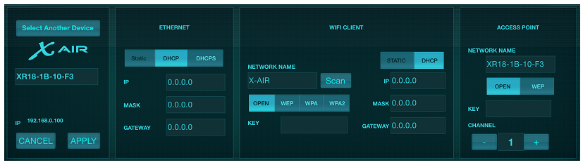
This screen allows the configuration of your wireless network connection. See the Network Connection chapter for details.
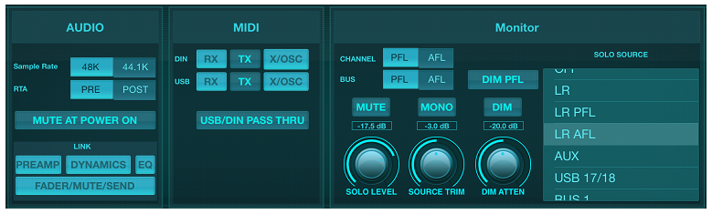
The Audio/MIDI tab allows global settings for audio, MIDI and monitor options.
The console operates at 48 kHz by default, but can be changed to 44.1 kHz. The RTA can be switched from pre to post-EQ to monitor the effect of EQ adjustments. Engage the 'Mute at Power On' function to avoid pops during start up. When the Link option is selected, adjacent channels are paired together. Aside from the fader settings being matched, the preamp, dynamics, EQ and fader/mute/sends can also be aligned.
Activate the desired MIDI transmit and receive options for the physical MIDI ports and the USB MIDI in the menu. Enabling DIN/USB Rx allows the XR to receive MIDI commands via physical or USB connection. Enabling DIN/USB Tx allows the XR to send MIDI data through physical or USB connection. USB-DIN Passthrough allows USB MIDI commands to be sent through the MIDI OUT jack.
DIN/USB-OSC enables text based OSC commands to be received via MIDI Sysex, either coming from USB or MIDI IN terminals.
Open Sound Control via Sysex F0 00 20 32 32 TEXT F7, with 'TEXT' being OSC strings in hex format, up to 39 kB in length.
Everything OSC related is described in our 'PUBLIC PART OSC archive' together with the parameters text file, which is distributed with every firmware update.
X-AIR_Remote-Control-Protocol_Rev2.ziphttps://mail.music-group.com/OWA/redir.aspx?C=vFVI2197zEpnR1dm_1L7qvNYTA5qI0AUxs94Qk-dL81MIErER6rVCA..&URL=https%3a%2f%2fconfluence.musictri.be%2fdownload%2fattachments%2f341054482%2fX-AIR_Remote-Control-Protocol_Rev2.zip%3fversion%3d1%26modificationDate%3d1472466936000%26api%3dv2)
The OSC paths and parameter values of the message that you’d like to convey need to be expressed as HEX Ascii characters one by one, including blanks and CR. The block of Hex characters (i.e. 2 digits each) can be copied to the ‘TEXT’ in the Sysex string. This enables users to access many functions inside the X-AIR mixer using standard MIDI transmission, for example, when running a DAW project.
Example message “/ch/01/eq/on 1” corresponds to the bold TEXT portion of the Sysex below, and it would switch the EQ in channel 1 on.
F0 00 20 32 32 2F 63 68 2F 30 31 2F 65 71 2F 6F 6E 20 31 F7
Note that all MIDI Config parameters should be unchecked in order for the BEHRINGER X-TOUCH control surface to control the X-AIR mixer via IP networks or MIDI.
5.15 Main EQ
There are 3 EQ options for the main and monitor buses: 6-band parametric, graphic, and “true” EQ. These are accessed by pressing the PEQ/GEQ/TEQ buttons on the right side.
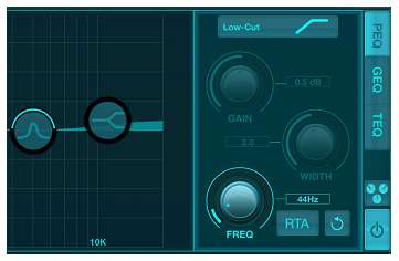
This parametric EQ functions the same as the channel EQ, but there are 6 bands available.
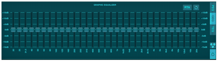
The GEQ and TEQ types appear to be identical, but the “true” EQ compensates for adjacent frequency adjustments. Most graphic equalizers have a multiplying effect when several neighboring bands are boosted or cut, causing an exaggerated EQ adjustment. The TEQ will have an EQ curve that is more indicative of the actual adjustments made on the sliders.