6. X AIR for Android
The X AIR applications for iOS, Android and Windows/Mac/Linux allow all of the physical controls and features normally found on analog mixers to be adjusted digitally, and also allow effects and routing to be fully adjusted, all from a remote location away from the input box. This results in a very compact, yet full-featured mixing solution that can be operated while moving about the venue or studio. This chapter will discuss the software’s functionality on an Android device.
6.1 Main View
The Main View screen provides access to all 16 channel faders, Aux in, and FX and bus levels, as well as navigation to preamp controls, meters, FX slots and more.
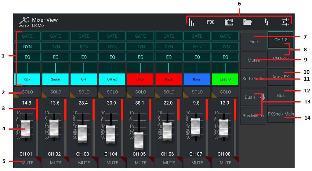
- The Channel Strip gives quick reference to the status of various preamp settings, and allows access to Gate, Dynamics, EQ, Pan and Input controls.
- Touch a channel’s Solo button to send the channel to the solo bus. The corner of the button will light yellow to indicate that a channel has been soloed.
- Each channel has a dedicated meter to monitor the input level. If the meter reaches the red clip lights, lower the gain control on the Input screen.
- The Channel Fader adjusts a channel’s level, or adjusts the aux/FX/bus send level, depending on which layer is selected on the right-hand side.
- Touch a channel’s Mute button to mute the channel. The button will light red when muted.
- Access the Meters, Effect Rack, Snapshots, Show/Scene, Routing and Setup pages by touching these buttons.
- Engaging the Fine button causes the faders to be adjusted in smaller increments, allowing more precise control.
- Select a channel bank 1-8 or 9-16 with these buttons.
- Access the Mute Group edit screen by pressing the Mutes button:
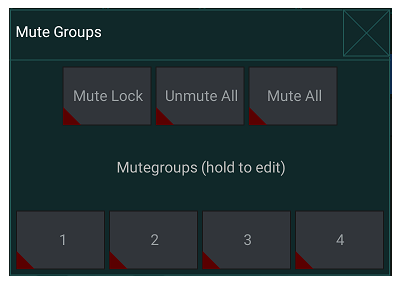
(note - this edit screen will be available in an upcoming software update)
Engage the Mute Lock button to prevent accidental muting of individual channels. Mute All and Unmute All are quick ways to fully mute or unmute all sources. Tap one of the 4 Mute Group buttons to mute the channels assigned to that group, and hold one of the buttons to edit which channels are assigned to the group.
- Access the Aux and FX return faders with this button.
- Activate the Sends on Faders function with this button. When active, the faders control the bus send levels for the currently active bus (see callout 13). Moving between the channel and Aux/FX layers allows the sends for those layers to be adjusted as well.
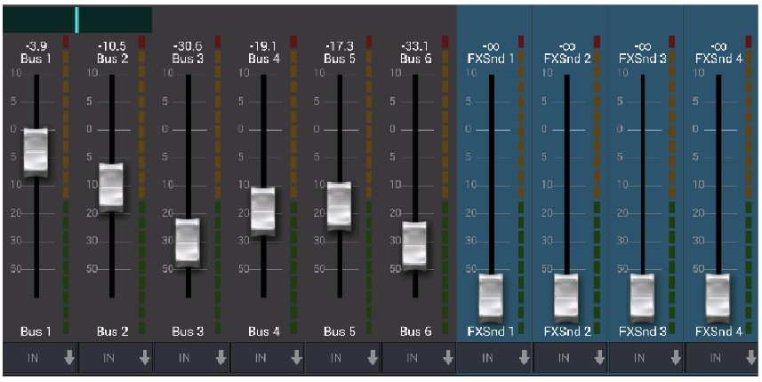
- Access the bus master faders with this button. Note that these will not be visible when the Sends on Faders function is active.
- When using the Sends on Faders function, the bus to which the channel signals are sent is selected with the button directly below the Sends on Faders button. Pressing the Bus Master button will allow the send level for the selected bus to be adjusted.
- Access the FX Send and Main LR faders with this button.
6.2 Input
The Input section allows adjustment of the most common preamp parameters such as gain, phase and phantom power. This is accessed from the Main View screen by pressing just above the Solo button in the channel strip area. By default, each channel will have a generic name such as “Ch 01” or “Bus 1”, but this can be customized in this section.
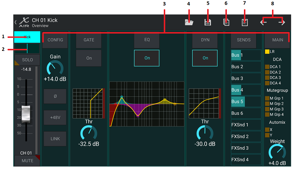
- Touch this top button to access the Scribble Strip page where a custom name and color can be selected.
- Adjust the Pan by touching this button.
- The on/off status and basic parameters for several preamp features can be adjusted on this page. To edit in detail, press Config, Gate, EQ, etc.
- Many preamp functions have factory settings that can be accessed from the folder icon.
- Current settings can be saved for later recall.
- Press this button to copy the current settings.
- Press this button to paste the recently-copied settings from one channel to another.
- Skip to the previous or next channel with the arrow buttons.
6.3 Config
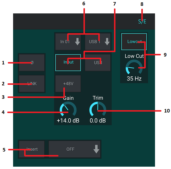
- Invert the phase with this button.
- Press the Link button to link the adjacent channel for stereo operation.
- Engage the 48 V phantom power by pressing and holding this button.
- Adjust the analog input Gain with this control.
- Engage an effect Insert and select the FX bus that will be inserted.
- The source for the channel’s physical input and USB input can be selected with these pull-down menus.
- Select whether the analog input or USB input appears at this channel.
- The S/E button appears at the top of many edit pages, and offers the option to view a simple or expanded set of controls, especially for the Gate and Dynamics pages.
- Engage the Low Cut with this button to remove unwanted low frequencies.
- Adjust the digital Trim for the USB input with this control.
6.4 Gate
The Gate tab allows a noise gate to be engaged and adjusted to remove unwanted noise. Using the S/E button, a simple or expanded set of parameters can be selected to accommodate various levels of mixing expertise. Presets can also be selected from the folder icon to automatically load settings that suit your application.
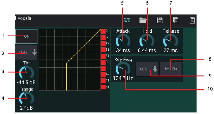
- Engage the gate with the ON button.
- The function menu allows various types of gates to be selected. The EXP 2, 3 and 4 settings create an extra-steep taper for signals that fall below the threshold. The Gate setting enables a more aggressive drop in volume for signals below the threshold. The Ducker setting attenuates the signal by a predetermined amount whenever the signal rises beyond the selected threshold.
- Adjust the Threshold that the audio must reach in order to bypass the gate or engage the Ducker.
- The Range parameter adjusts the amount of attenuation for the Gate and Ducker.
- Adjust the Attack knob to set how quickly the gate takes effect when the input signal drops below the threshold.
- Adjust the Hold knob to set how long the input signal must surpass the threshold before bypassing the gate.
- Adjust the Release knob to set how quickly the gate releases after the audio rises above the threshold.
- Engage the key filter with the Key On button.
- Select a low cut, high cut or mid peak frequency and bandwidth/slope for the key filter.
- Select the frequency for the key filter.
6.5 EQ
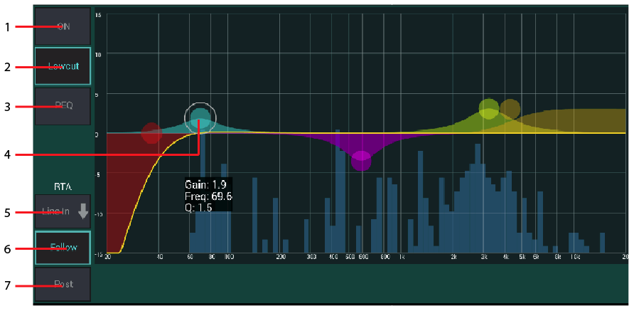
- Engage the EQ with the ON button.
- Engage the Lowcut button to remove unwanted low frequencies.
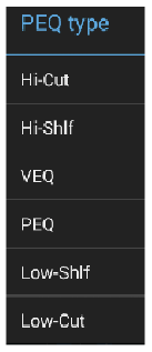
- Select the type of EQ for the selected band. This menu will only be available when one of the 4 bands are active, not including the lowcut.
- Drag the band button left and right to determine the specific frequency, and move it up and down to determine the amount of boost or cut. Use a pinch or spread gesture (zoom in/out) to alter the bandwidth/Q.
- Select the source for the RTA to display.
- To automatically send the channel that you are currently editing to the RTA, press the Follow button.
- Press the Post button to display the post-EQ results in the RTA.
Graphic EQ
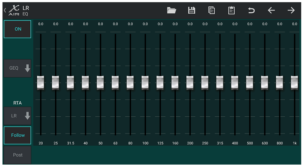
There are 3 EQ options for the Main LR and Aux buses: 6-band parametric, graphic, and “true” EQ. The parametric EQ functions the same as the channel EQ, only with 6 bands available. The GEQ and TEQ types appear to be identical, but the “true” EQ compensates for adjacent frequency adjustments. Most graphic equalizers have a multiplying effect when several neighboring bands are boosted or cut, causing an exaggerated EQ adjustment. The TEQ will have an EQ curve that is more indicative of the actual adjustments made on the sliders.
6.6 Dynamics
A channel’s dynamics can be adjusted on this page. A compressor is useful for reducing the dynamic range of a signal, allowing the perceived volume in the mix to be raised without clipping. An expander can add dynamics by attenuating a signal when it drops below the predetermined threshold. Using the S/E button, a simple or expanded set of parameters can be selected to accommodate various levels of mixing expertise.
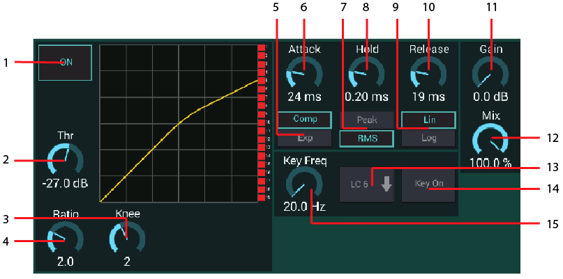
- Engage the processor with the ON button.
- Adjust the Threshold at which the compressor begins to take effect. Audio that falls below this setting will remain unaffected.
- Adjust the Knee to allow the compressor to have a more gradual effect on the signal. When the Knee is set fully to the left (hard knee), any signals that rise above the threshold will receive the full compression ratio right away.
- Adjust the Ratio to determine how aggressively the dynamics are affected.
- Select between a compressor or expander to set the action of the dynamics processor. While a compressor reduces a signal’s dynamics, an expander increases the dynamic range.
- Adjust the Attack knob to set how quickly the compressor takes effect when the input signal rises above the threshold.
- Select between Peak or RMS input response. RMS is most common in compressors, and responds to the average level of incoming audio, whereas the Peak setting responds to brief spikes in loudness that would be allowed through when set to RMS.
- Adjust the Hold knob to set how long the compressor takes to enter the release cycle once the audio drops below the threshold.
- Select between an aggressive Linear or smooth Logarithmic operation.
- Adjust the Release knob to set how quickly the compressor releases after the audio drops below the threshold.
- Use the Gain knob to compensate for changes in level caused by the processor.
- Adjust the Mix knob to determine how much of the signal is left unaffected by the processor.
- Select a high cut, low cut or mid peak frequency and bandwidth/slope for the key filter.
- Engage the key filter with the Key On button.
- Select the frequency for the key filter.
6.7 Sends
The Sends screen allows the currently selected channel’s signal to be routed to the 6 Aux outputs and to the 4 Effects processors. Aux and Effects routing can also adjusted using the fader banks on the right-hand side of the Main View screen. The signal can be routed to the buses from specific points in the preamp chain, such as pre or post EQ (the S/E button must be active).
6.8 Main
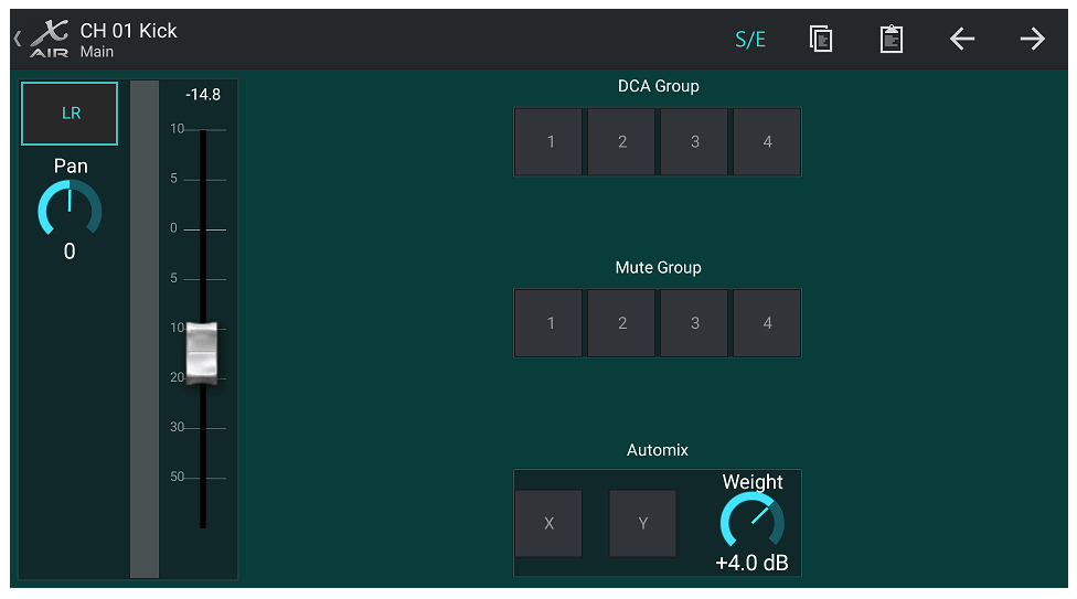
When the LR button is active, the channel is assigned to the main bus. For sources that are not intended for the audience to hear, such as click tracks, removing the channel from the main bus eliminates the potential to accidentally mix that source into the mains.
This page also allows the channel to be quickly assigned to a DCA, Mute Group or Automix group.
The Auto Mix function is very useful for meetings or panel discussions where multiple microphones are used for speech. The mic channels can be assigned to one of two auto mix groups, which will automatically attenuate the channels that are not currently receiving signal. Click the X or Y auto mix buttons in the Main tab to assign several channels to an auto mix group.
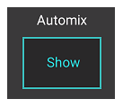
Navigate to the Setup - Preferences tab and engage the Show button under Automix. This will cause an Automix X and Y button to appear on the Main View screen.
Whenever an auto mix bus is engaged, a blue gain reduction meter will indicate the amount of signal reduction for any channels assigned to the bus. This allows the current speaker to be heard clearly while suppressing any noise from the other microphones. In each channel's Main tab, a Weight knob is included which allows certain channels to be attenuated more or less to compensate for louder voices or more sensitive microphones.
6.9 Meters
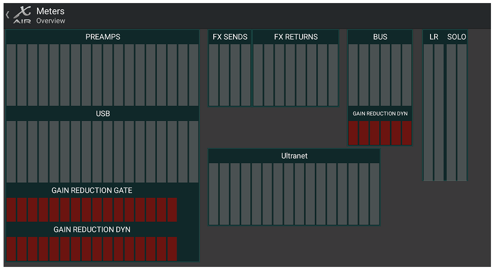
The Meters tab allows easy monitoring of all analog and digital levels, including USB channels, Buses, Ultranet outputs, and the Main and Solo buses.
6.10 Effect Rack
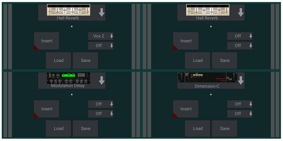
The Effect Rack page is accessed via the “FX” icon at the top of the Main View screen. There are 4 slots where various effects can be selected and adjusted to suit the application. Tap on the effect slot to select an effect and adjust the available parameters.
6.11 Snapshots
The snapshot function allows specific bits of information to be saved for immediate recall. For example, quick changes can be selected for different acts of a play, performances in a music festival with several bands, or different church services.
Click the camera icon at the top of the main screen. A window will open with a list of parameters to select for recall. You can select individual channels/parameters that will be recalled from a previously saved snapshot, or click the ‘All’ button to choose everything in a category. There may be channels, buses, parameters, etc. that should remain unaffected throughout an event, so this method is beneficial for its highly specific method of recall.
To save a snapshot, press and hold one of the slots in the left-hand list. A new entry will appear in the list where you can type in a name for the new snapshot. To recall a previously-saved snapshot, press and hold the item in the list and then select the Load option. Note that all aspects of the current arrangement will be saved to a new snapshot slot, and the specific elements of that snapshot can be selected upon recall.
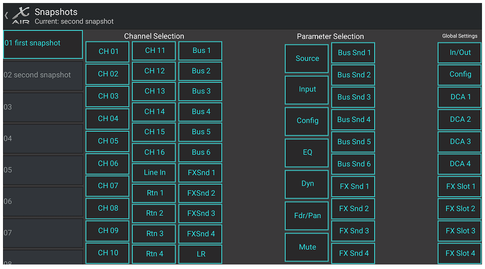
The snapshot recall parameters are listed in 3 categories: channel, parameter and global.
The Channel Section lets you determine which channels or bus masters will be affected during recall.
The Parameter Section lets you determine which specific preamp elements will be recalled for the channels and buses selected in the Channel Section above. Source affects the input vs. USB selection, Input recalls basic preamp settings such as phantom and gain setting, and Config recalls the configuration. EQ, Dyn, Fdr/Pan and Mute recall these settings for the selected channels, and the bus/FX sends can be individually assigned for recall.
Global Settings allow the input/output routing to be recalled, as well as global configuration, DCA assignments, and FX block settings.
To delete a snapshot that is no longer necessary, select it from the list and then select Delete.
6.12 Scenes and Shows
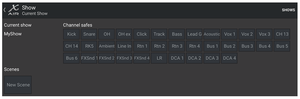
The Scenes/Shows page is accessed via the folder icon at the top of the Main View screen. This page allows you to save, edit and recall specific scenes or entire shows. To prevent certain channels or buses from being affected by scene or show recalls, arm the desired sources in the ’Channel safes’ section.
6.13 Routing
The Routing menu is accessed via the up/down arrow icon at the top of the Main View screen. This allows the specific routing of input, output, USB and monitor buses to be adjusted freely.
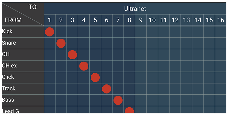
Tap inside an empty box in the grid to move the orange dots and reassign the source for input channels, USB channels and P16 monitoring sources. Modifications to the Inputs/USB routing can be reset by pressing the revert button on the far right. The USB sends and inputs can be selected from a menu in the folder icon, or they can be moved manually.
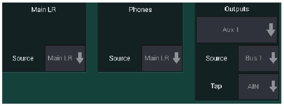
The Routing – Outputs page allows the Main LR, Phones, Aux and P16 sources to be reassigned.
6.14 Setup
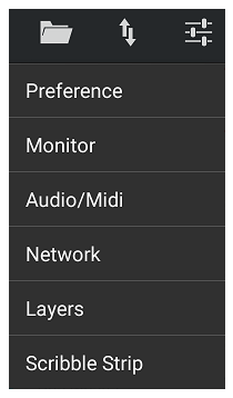
The Setup menu is accessed via the top right corner of the Main View screen. This allows access to several global settings, network configurations and layout features.
Preferences
The Preferences screen allows the auto mix X and Y buttons to be viewed on the Main View screen.
Monitor
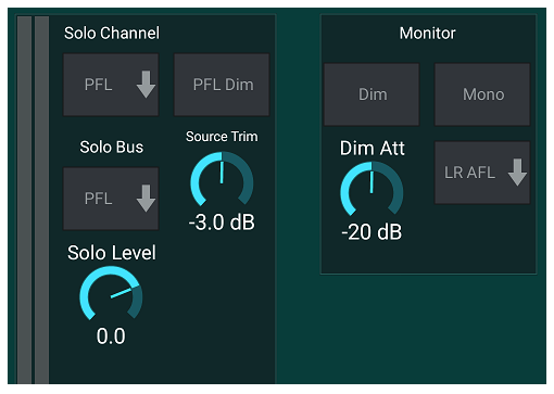
The Solo Channel and Solo Bus can operate in pre-fader or after-fader listen mode. The solo level can be adjusted if necessary as well. A dimmer can be engaged and adjusted to cause a drop in volume for the program material whenever a signal is soloed. The solo bus can operate in mono or stereo. The source and tap for the monitor source can be selected from the pull-down menu, which will be heard when no sources are soloed.
Audio/MIDI
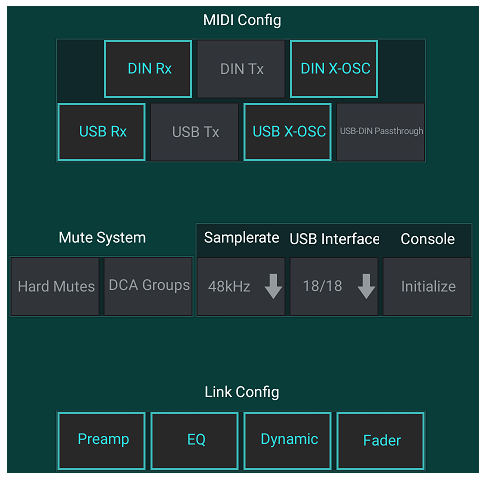
The Setup – Audio/MIDI page allows editing of MIDI receive (Rx) and transmit (Tx) settings, as well as several global system parameters.
Activate the desired MIDI transmit and receive options for the physical MIDI ports and the USB MIDI in the menu. Enabling DIN/USB Rx allows the XR to receive MIDI commands via physical or USB connection. Enabling DIN/USB Tx allows the XR to send MIDI data through physical or USB connection. USB-DIN Passthrough allows USB MIDI commands to be sent through the MIDI OUT jack.
DIN/USB-OSC enables text based OSC commands to be received via MIDI Sysex, either coming from USB or MIDI IN terminals.
Open Sound Control via Sysex F0 00 20 32 32 TEXT F7, with 'TEXT' being OSC strings in hex format, up to 39 kB in length.
Everything OSC related is described in our 'PUBLIC PART OSC archive' together with the parameters text file, which is distributed with every firmware update.
X-AIR_Remote-Control-Protocol_Rev2.zip
The OSC paths and parameter values of the message that you’d like to convey need to be expressed as HEX Ascii characters one by one, including blanks and CR. The block of Hex characters (i.e. 2 digits each) can be copied to the ‘TEXT’ in the Sysex string. This enables users to access many functions inside the X-AIR mixer using standard MIDI transmission, for example, when running a DAW project.
Example message “/ch/01/eq/on 1” corresponds to the bold TEXT portion of the Sysex below, and it would switch the EQ in channel 1 on.
F0 00 20 32 32 2F 63 68 2F 30 31 2F 65 71 2F 6F 6E 20 31 F7
Note that all MIDI Config parameters should be unchecked in order for the BEHRINGER X-TOUCH control surface to control the X-AIR mixer via IP networks or MIDI.
The console defaults to “soft mutes”, meaning that if a channel has been specifically muted, and is also a part of a mute group, when the mute group is unmuted, the channel that was specifically muted will also be unmuted. Selecting Hard Mutes will cause a channel that has been muted with its dedicated Mute button will remain muted even if a mute group to which it belongs is unmuted. DCA Groups normally just control volume levels without actually having audio routing through them. However, engaging DCA Groups in the Mute System will enable channels to be muted via DCA group assignments.
The console can operate at 48 kHz or 44.1 kHz. Mute the main LR fader before changing clock rates as pops can occur.
The X18/XR18 has an 18x18 channel interface built-in, but sometimes this is overkill for a recording session. For overdubs and simple tracking, the 2x2 interface is more efficient and easier on processing power.
Click the Initialize button to reset all system parameters. All settings will be lost, so make sure to save any scenes or shows to a PC hard drive first.
When the Link option is selected in a channel's Config page, the adjacent channel is linked as a stereo pair. Aside from the fader settings being matched, the preamp, dynamics, EQ and fader/mute/sends can also be aligned, depending which items are activated at the bottom of the Audio/MIDI page.
Network
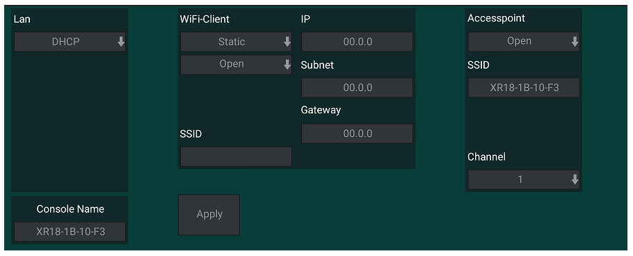
This screen allows the configuration of your wireless network connection. See the Network Connection chapter for details.
Layers
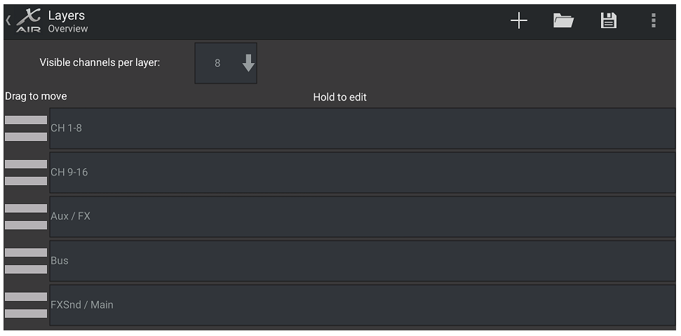
The Setup – Layers page allows the order of channels and buses to be altered. By default, only 8 channels are visible on the Main View screen at one time, but this can be edited to allow, for example, all 16 input channels to be seen at once. A new layer can also be created to contain a custom mix of inputs and buses. By increasing the visible channels per layer to 9, the Main LR fader could be added to all of the fader banks so it is always available for adjustment.

Custom layers can be saved and recalled later, and the layers can be restored to their default settings. The Setup menu also allows quick access to the Scribble Strips for changing channel names and colors.
Scribble Strip
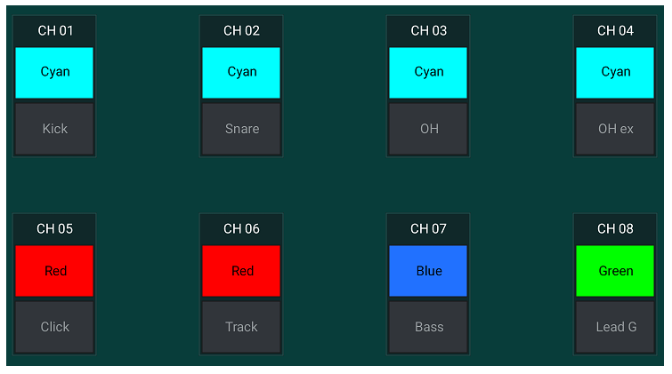
The Scribble Strip page allows a custom name and color to be assigned for each channel, bus, FX send/return, and DCA group.