7. X AIR for PC
The X AIR applications for iOS, Android and Windows/Mac/Linux allow all of the physical controls and features normally found on analog mixers to be adjusted digitally, and also allow effects and routing to be fully adjusted, all from a remote location away from the input box. This results in a very compact, yet full-featured mixing solution that can be operated while moving about the venue or studio. This chapter will discuss the software's functionality on a laptop/desktop running Windows, OS X or Linux.
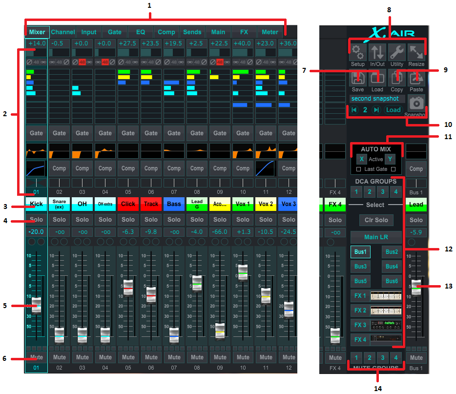
7.1 Main View and Mixer Tab
-
The Navigation Tabs allow quick access to various edit menus.
-
The Channel Strip area gives a quick reference to the status of phantom power, aux send levels, pan, etc., The gain, aux levels, FX send levels and pan can be adjusted by clicking and dragging left or right inside the respective section. Click the Gate, EQ and Comp sections to jump to the edit pages for that channel.
Note – the following items are always visible regardless of which tab is selected:
-
Left-click the channel number to select that channel. Right-click to change the name and color of the channel.
-
Touch a channel's Solo button to send the channel to the solo bus. The button will light orange to indicate that the channel has been soloed.
-
The Channel Fader adjusts a channel's level, or adjusts the aux/FX send level, depending on which layer is selected on the right-hand side.
-
Click a channel's Mute button to mute the channel. The button will light red when muted.
-
Use the Save and Load icons to save and recall show scenes and saved channel settings.
-
Access the Setup and Routing screens via the icons in the upper right corner. The Utility feature is currently inactive, but will be integrated in future firmware updates. The Resize button allows the window to automatically fit various screen resolutions up to 4k, as well as conform to a custom size.
-
Use the Copy and Paste buttons to transfer information between channels.
-
The Snapshot feature lets you save specific bits of information for later recall. Clicking the Snapshot icon brings up a window where the new snapshot can be named and the content selected for saving. Dedicated controls allow the saved snapshots to be shuffled through and loaded directly from the main mixer view.
-
Engage the Auto Mix X and Y buses here. See section 7.14 for details.
-
The Fader Bank buttons determine which layer is active in the faders. When set to Main LR, the faders adjust the channel volume levels sent to the main bus, and the main output is adjusted with the far-right fader. When one of the bus or FX layers are selected, the faders adjust each channel's send level to that bus for monitoring or effects routing. The overall bus level is adjusted with the far-right fader. To assign a channel to a DCA, select the DCA group 1-4 and then click the small circle located above each channel fader that you want to assign to that group. The group number will be indicated in the circle.
-
The main level fader adjusts the output of the currently-selected bus.
-
The 4 Mute Group buttons engage the mute groups. Click one of the 4 small boxes below each channel fader to assign that channel to a particular mute group.
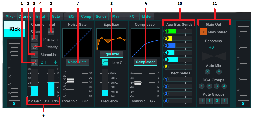
7.2 Channel Tab
The Channel tab allows quick access to the most common preamp parameters, as well as basic control over the noise gate, compressor and bus sends. Most of the adjustments on this tab can also be found in greater detail on other tabs.
-
Click the FX button to engage an insert effect. The specific FX block is selected with the adjacent pull-down menu.
-
The Stereo Link button allows a channel to be paired with the adjacent channel in a stereo pair. The fader level, gain setting, bus sends, etc. will be the same between the 2 channels, and the pan will default to hard left and right. The odd-numbered channel will always be the lower of the pair.
-
The Phantom button engages the 48V phantom power for use with condenser microphones and active DI boxes.
-
The Polarity button inverts the phase.
-
Click the USB button to route the USB return signal to the selected channel instead of the analog input.
-
The analog Mic Gain and digital USB Trim can be adjusted independently, though only one source can be used at a time.
-
The Noise Gate can be engaged and the threshold can be adjusted from this page. More detailed controls are available on the Gate tab.
-
The Equalizer and Low Cut can be engaged here, as well as the low cut frequency.
-
The Compressor can be engaged and its threshold adjusted here. More detailed controls are available on the Comp tab.
-
The channel Aux Bus Sends can be adjusted here as well as the Sends tab.
-
The Main Out section allows the channel to be routed to or removed from the main bus. The pan can also be adjusted, and the Auto Mix, DCA Group and Mute Group assignments can be selected here as well.
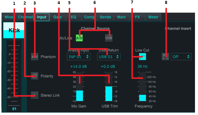
7.3 Input Tab
The Input tab allows adjustment of the most common preamp parameters as well as specific routing for the input and insert.
-
The Stereo Link button allows a channel to be paired with the adjacent channel in a stereo pair. The fader level, gain setting, bus sends, etc. will be the same between the 2 channels, and the pan will default to hard left and right. The odd-numbered channel will always be the lower of the pair.
-
The Polarity button inverts the phase.
-
The Phantom button engages the 48V phantom power for use with condenser microphones and active DI boxes.
-
The analog Mic Gain and digital USB Trim can be adjusted independently, though only one source can be used at a time.
-
The analog input and USB input channels default to a 1:1 relationship to the channel number, but can be re-routed using the pull-down menus.
-
Select whether the analog mic/line input or the USB input appears in the channel.
-
Engage the Low Cut and adjust the specific frequency to remove unwanted lows.
-
Click the FX button to engage an insert effect. The specific FX block is selected with the adjacent pull-down menu.
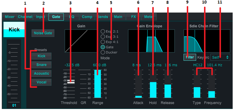
7.4 Gate Tab
The Gate tab allows a noise gate to be engaged and adjusted to automatically remove unwanted noise.
-
Select one of the 4 Presets to automatically optimize the parameters for one of these common sources.
-
Engage the Noise Gate with this button.
-
Adjust the Threshold that the audio must reach in order to bypass the gate or engage the ducker.
-
The Range parameter adjusts the amount of signal attenuation for the Gate and Ducker settings.
-
Select the type of effect from the 5 options. Expander effects are available with 2:1, 3:1 and 4:1 ratios which reduce the output by varying amounts, allowing a natural sounding reduction of signals that don't reach the selected threshold. The Gate setting enables a more aggressive drop in volume for signals below the threshold. An additional Range parameter adjusts the amount of attenuation. The Ducker setting attenuates the signal by an adjustable amount whenever the signal rises beyond the selected threshold. The Range parameter adjusts the amount of attenuation for this setting as well.
-
Adjust the Attack parameter to set how quickly the gate takes effect when the input signal drops below the threshold.
-
Adjust the Hold parameter to set how long the input signal must surpass the threshold before bypassing the gate.
-
Adjust the Release parameter to set how quickly the gate releases after the audio rises about the threshold.
-
Engage the key Filter with this button.
-
Select the type of filter and frequencies with these faders.
-
Select a channel or bus for the side chain filter from the pull-down menu.
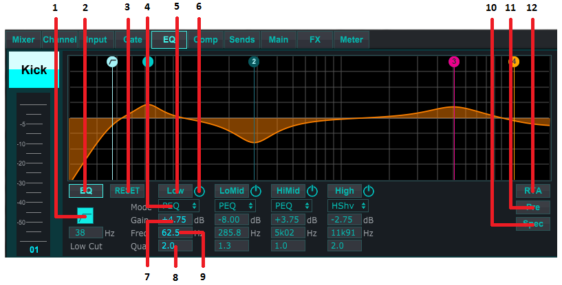
7.5 EQ Tab
-
Engage the Low Cut and adjust the specific frequency to remove unwanted lows.
-
Turn the equalizer on and off with the PEQ button. This maybe be labeled differently for bus equalizers because they also have graphic EQ options.
-
Use the Reset button to return all bands to their default settings. A confirmation box will pop up to prevent accidental resets.
-
Select the Mode from the pull-down menu. PEQ types will often be used for the first 3 bands, and a high cut or high shelf for the 4th band.
-
The currently-active band will be indicated on this button.
-
Click this button to turn a specific band on and off. This is useful for A/B testing how an adjustment affects the signal.
-
The gain adjustment for each band can be manually entered here, or you can click and drag the band's corresponding number up and down.
-
The bandwidth (Q) can be manually entered here.
-
Each band's specific frequency can be manually entered, or you can click and drag the band's number to the desired frequency.
-
Engage the Spectrograph function to change from the standard RTA view to a spectrogram, which displays the signal energy over time. This can be useful for identifying feedback or phasing problems.
-
Press the Pre button to display the RTA pre-EQ rather than post-EQ.
-
Engage the RTA (Real Time Analyzer) with this button.
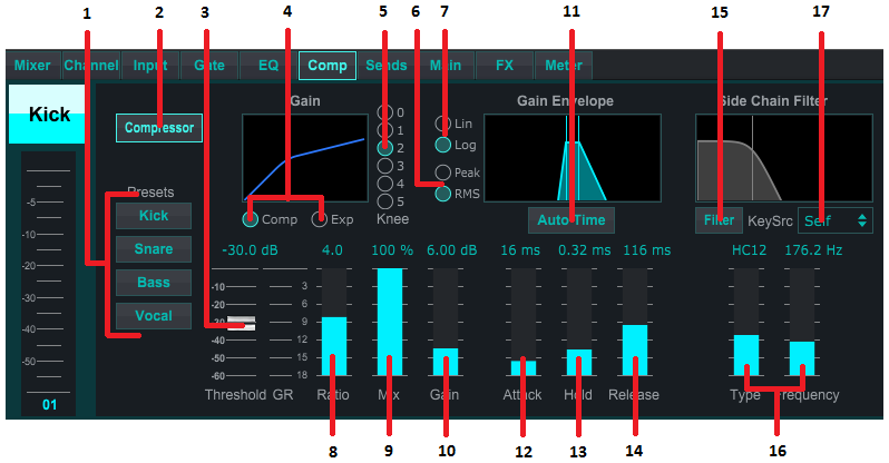
7.6 Comp Tab
-
Select one of the 4 Presets to automatically optimize the parameters for one of these common sources.
-
Engage the Compressor with this button.
-
Adjust the Threshold at which the compressor begins to take effect. Audio that falls below this setting will remain unaffected.
-
Select between a Compressor or Expander to set the action of the dynamics processor. While a compressor reduces a signal's dynamics, an expander increases the dynamic range.
-
Select a Knee angle to set how gradual the compressor takes effect. When set to 0, any signals that rise above the threshold will receive the full compression ratio.
-
Select between Peak and RMS input response. RMS is most common in compressors and responds to the average level of incoming audio, whereas the Peak setting responds to brief spikes in loudness that would be allowed through when set to RMS.
-
Select between an aggressive Linear or smooth Logarithmic operation.
-
Adjust the Ratio to determine how aggressively the dynamics are affected.
-
Adjust the Mix to determine how much of the signal is left unaffected by the processor.
-
Adjust the Gain to compensate for changes in level caused by the processor.
-
Engage the Auto Time to allow several of the more advanced parameters to be automatically adjusted according to the input signal.
-
Adjust the Attack to set how quickly the compressor takes effect when the input signal rises above the threshold.
-
Adjust the Hold to set how long the compressor takes to enter the release cycle once the audio drops below the threshold.
-
Adjust the Release to set how quickly the compressor releases after the audio drops below the threshold.
-
Engage the key Filter with this button.
-
Select the type of filter and frequencies with these faders.
-
Select a channel or bus for the side chain filter from the pull-down menu.
7.7 Sends Tab
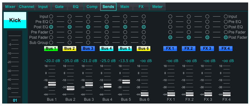
The Sends tab allows the currently-selected channel's signal to be routed to the 6 Aux buses and to the 4 FX processors. These adjustments can also be made on the Channel tab, or by selecting one of the Fader Bank layers on the lower right-hand side of the main view screen. The signal can be routed to the buses from specific points in the preamp chain, such as pre or post EQ and pre or post fader. Clicking the globe icon will enable changes to the tap point (pre/post fader, etc) to take effect on all channels.
7.8 Main Tab
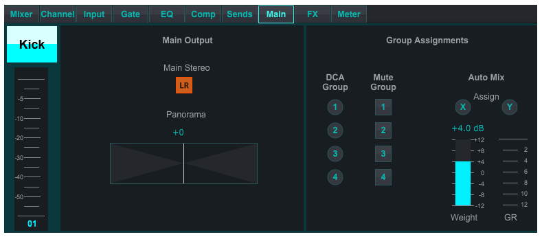
All of the controls on the Main tab are also accessible from the Channel tab. The channel's signal can be unassigned from the main output, which is useful when recording sources that aren't meant to be heard by the audience, or for sources such as click tracks that are only meant for the performers' mixes and not the main speakers. The channel's pan control can be adjusted and DCA, Mute Group and Auto Mix assignments can be made as well.
7.9 FX Tab
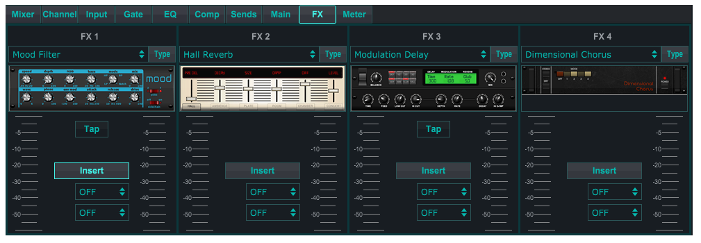
The FX tab has 4 effect processors that can be routed and adjusted to various channels and buses. A new effect can be selected by clicking the pull-down menu where the current effect's name is displayed, or by clicking the Type button which also shows a graphic view of each effect. Once a desired effect is selected, click on the graphic to bring up the edit window where the specific parameters can be adjusted. If applicable, a tap tempo button is available to manually enter the rate of delays or choruses. The button will flash to indicate the tempo. Click the Insert button to engage the effect as an insert instead of side-chain. Select the channel or bus assigned to the effect with the pull-down menu. See the Effects Overview chapter for more details.
7.10 Meter Tab
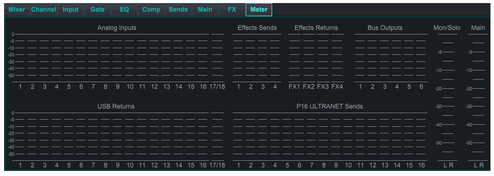
The Meter tab allows easy monitoring of all analog and digital levels, including USB channels, Buses, Ultranet outputs, and the Main and Solo buses.
7.11 Setup Menu
The Setup menu allows the wireless connection to be configured and allows various global parameters to be selected and adjusted.
Connection Tab
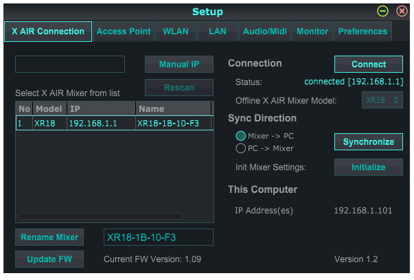
After you connect your computer to the internal Access Point or external router, the software will likely automatically recognize the mixer and ask to connect. Once connected, a prompt will ask if you would like to transfer settings from the mixer to PC, or from the PC to the mixer. Click 'cancel' if you don't want to sync settings. The Connection tab also allows you to manually assign an IP address. If you have firmware 1.09 or later, you can update the firmware directly from this screen as well.
Note - save your settings to your computer's hard drive before updating the firmware!
By default, a generic name, such as XR18-1B-10-F3, will be assigned to your mixer. This can be changed to something more specific and recognizable. The console can also be initialized back to its factory state, but be aware that all settings will be erased. We highly recommend using the Save function to store any important scenes to your computer's hard drive.
Access Point, WLAN, LAN Tabs
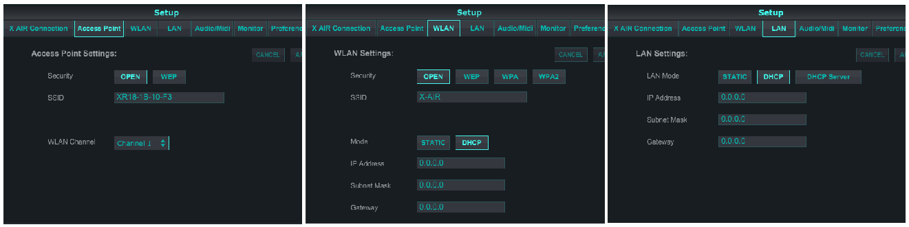
The Access Point, WLAN and LAN tabs allow the wireless connection to be configured. See the 'Network Connection' chapter for details.
Audio/MIDI Tab
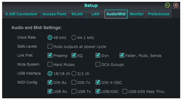
Activate the desired MIDI transmit and receive options for the physical MIDI ports and the USB MIDI in the menu. Enabling DIN/USB Rx allows the XR to receive MIDI commands via physical or USB connection. Enabling DIN/USB Tx allows the XR to send MIDI data through physical or USB connection. USB-DIN Passthrough allows USB MIDI commands to be sent through the MIDI OUT jack.
DIN/USB-OSC enables text based OSC commands to be received via MIDI Sysex, either coming from USB or MIDI IN terminals.
Open Sound Control via Sysex F0 00 20 32 32 TEXT F7, with 'TEXT' being OSC strings in hex format, up to 39 kB in length.
Everything OSC related is described in our 'PUBLIC PART OSC archive' together with the parameters text file, which is distributed with every firmware update.
X-AIR_Remote-Control-Protocol_Rev2.zip
The OSC paths and parameter values of the message that you’d like to convey need to be expressed as HEX Ascii characters one by one, including blanks and CR. The block of Hex characters (i.e. 2 digits each) can be copied to the ‘TEXT’ in the Sysex string. This enables users to access many functions inside the X-AIR mixer using standard MIDI transmission, for example, when running a DAW project.
Example message “/ch/01/eq/on 1” corresponds to the bold TEXT portion of the Sysex below, and it would switch the EQ in channel 1 on.
F0 00 20 32 32 2F 63 68 2F 30 31 2F 65 71 2F 6F 6E 20 31 F7
Note that all MIDI Config parameters should be unchecked in order for the BEHRINGER X-TOUCH control surface to control the X-AIR mixer via IP networks or MIDI.
The console can operate at 48 kHz or 44.1 kHz. Mute the main LR fader before changing clock rates as pops can occur.
Engage the Safe Levels function to automatically mute the outputs during a power cycle. This is particularly useful for situations where the mixer is always connected to a PA system or monitoring setup.
The Link Preferences allow specific preamp elements to be synchronized when adjacent channels are linked.
The console defaults to "soft mutes", meaning that if a channel has been specifically muted, and is also a part of a mute group, when the mute group is unmuted, the channel that was specifically muted will also be unmuted. Selecting Hard Mutes will cause a channel that has been muted with its dedicated Mute button will remain muted even if a mute group to which it belongs is unmuted. DCA Groups normally just control volume levels without actually having audio routing through them. However, engaging DCA Groups in the Mute System will enable channels to be muted via DCA group assignments.
The X18/XR18 has an 18x18 channel interface built-in, but sometimes this is overkill for a recording session. For overdubs and simple tracking, the 2x2 interface is more efficient and easier on processing power.
Various send (Tx) and receive (Rx) preferences are selectable for the MIDI configuration.
Monitor Tab
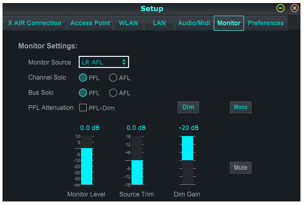
The monitor source defaults to the main LR (post-fader), but you can select a bus, aux, USB 17/18 or a combination of buses. Soloed channels and buses can be monitored pre or post-fader. PFL attenuation can be engaged and the relative levels for monitor and source can be set. Click the DIM button to enable dimming and select the attenuation level. The monitor bus can be set to mono and can be muted from this page.
Preferences Tab
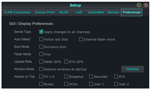
Select the 'Apply changes to all channels' option if you would like changes made to bus send taps (pre/post-EQ, etc) to be applied to all channels.
Auto Select options allow the last soloed channel to be selected automatically, and allow a channel to be automatically selected whenever its fader is adjusted.
Exclusive solo mode allows only one source to be soloed at a time. Pressing a channel's Solo button will automatically un-solo previously soloed channels.
The 'Fine' fader mode allows adjustments to the faders to occur more gradually, allowing more precise control when making small changes.
The update rate defaults to 100%, meaning the meters and RTA display immediate feedback of the audio signals. However, this can be adjusted to 50%, which shows less detail but also conserves on processing power.
The configuration of the application's windows can be stored and recalled upon launch. Click the Initialize button to clear the stored window configuration.
Use the Always on Top selection to keep certain windows in view regardless of other windows being adjusted.
7.12 Snapshot Page
The snapshot function allows specific bits of information to be saved for immediate recall. For example, quick changes can be selected for different acts of a play, performances in a music festival with several bands, or different church services.
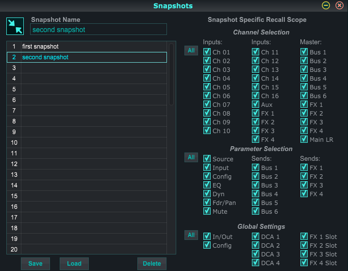
Click the ‘Snapshots’ icon on the right hand side of the main screen. A window will open with a list of parameters to select for recall. You can select individual channels/parameters that will be recalled from a previously saved snapshot, or click the ‘All’ button to choose everything in a category. There may be channels, buses, parameters, etc. that should remain unaffected throughout an event, so this method is beneficial for its highly specific method of recall.
To save a snapshot, click one of the slots in the left-hand list. A new entry will appear in the list where you can type in a name for the new snapshot. Note that all aspects of the current arrangement will be saved to a new snapshot slot, and the specific elements of that snapshot can be selected upon recall.
The snapshots recall parameters are listed in 3 categories: channel, parameter and global.
The Channel Section lets you determine which channels or bus masters will be affected during recall.
The Parameter Section lets you determine which specific preamp elements will be recalled for the channels and buses selected in the Channel Section above. Source affects the input vs. USB selection, Input recalls basic preamp settings such as phantom and gain setting, and Config recalls the configuration. EQ, Dyn, Fdr/Pan and Mute recall these settings for the selected channels, and the bus/FX sends can be individually assigned for recall.
Global Settings allow the input/output routing to be recalled, as well as global configuration, DCA assignments, and FX block settings.
To delete a snapshot that is no longer necessary, select it from the list and click Delete.
7.13 Utilities
Utilities offer convenient editing and customization of items that are not easily controlled on other windows or menus.
RTA Utility
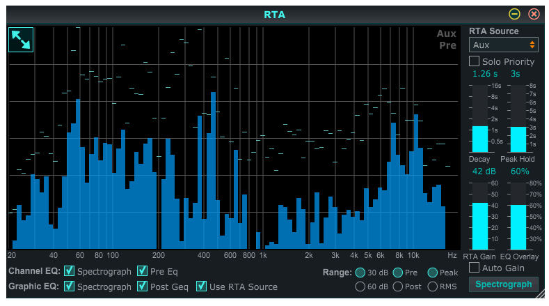
The RTA utility allows customization of the appearance and functionality of the real time analyzer. The RTA Source pull-down menu allows a specific channel or bus to be fixed to the RTA, or the RTA can follow the active channel. Select Solo Priority to send any soloed channel to the RTA.
The Decay adjustment controls how quickly the frequency bands fall after reaching their initial indication. Peak Hold will leave a small marker to indicate the peak measurement over a longer period of time while still monitoring the fine audio activity. RTA Gain compensates for audio levels, ensuring accurate readings. Select the Auto Gain feature to automatically select an appropriate RTA gain level. The EQ overlay adjustment controls the opacity of the RTA when viewing channel EQ curves. Select Spectrograph to view the audio energy across the spectrum, where blue represents lower levels and red indicates higher levels. Note that this only affects the RTA utility window and not the individual channel EQs.
Channel and Graphic EQs can be preassigned to have spectrograph RTAs, and can operate as pre or post-EQ. These selections can be overridden on the channel/bus EQ tab. Select the 'Use RTA Source' option if you want to view a source's RTA while adjusting another channel's EQ.
Select a 30 or 60 dB gain range, and pre or post EQ results. Select Peak to monitor the rapid changes in frequency response, or RMS to view an average response over a longer period of time.
Buses Utility
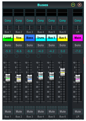
The Buses utility window gives convenient access to all of the channel strip functions of all 6 buses and the main LR at the same time. This window can be left open so that changes can be made without having to select individual buses in the main window.
DCA Utility
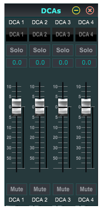
Similar to the Buses utility, the DCA utility window allows all 4 DCA groups to be easily monitored and adjusted.
A custom set of channels, buses and/or DCA groups can also be configured in 2 user-defined windows. This has the added feature of expanding the channel strip to include the gain level, bus sends, and other information that is normally visible in the mixer tab in the main window.
7.14 Auto Mix
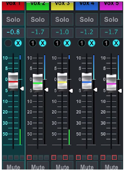
The Auto Mix function is very useful for meetings or panel discussions where multiple microphones are used for speech. The mic channels can be assigned to one of two auto mix groups, which will automatically attenuate the channels that are not currently receiving signal. Click the X or Y auto mix buttons on the right side of the main window, then click the right-hand circle just above each channel fader that you want to assign to the auto mix. An X or Y will appear in the circle to indicate the assignment.
Whenever the auto mix bus is engaged, a blue gain reduction meter will indicate the amount of signal reduction. This allows the current speaker to be heard clearly while suppressing any noise from the other microphones. A white arrow also appears next to each fader assigned to the auto mix bus, which allows certain channels to be attenuated more or less to compensate for louder voices or more sensitive microphones.
For situations when one person is speaking for extended periods of time, it may be helpful to select the Last Gate box beneath the auto mix button. This keeps the most recently active channel open, preventing unwanted artifacts of the gate opening and closing during pauses in speech.
We have a tutorial video that explains this feature in our 'X AIR How To' playlist on YouTube.